
 Contact Us
 Language
 English
 русский
 Español
Main fan Product Name Air volume All-in Medium temperature Conveying medium Main fan 1000-30000...
See Details
Content
A centrifugal fan is a machine that moves air or gas by spinning it outward. Gas enters at the centre of a rotating impeller, is caught between the blades, and is thrown toward the outer edge of the casing, where it leaves through an outlet. The impeller adds velocity to the gas; the scroll-shaped housing then slows that gas down and converts velocity into static pressure. Every other detail — impeller diameter, blade shape, material, bearing arrangement, drive type — exists to make that one conversion work at a specific duty point.
That is the short answer. In industrial practice the fan is rarely the first item chosen in a system and almost always the first one blamed when the system underperforms.
Follow one parcel of gas through a single-inlet fan. It is drawn into the inlet cone, which guides it into the eye of the impeller. The blades force it outward against the casing. Because the gas leaves at roughly a right angle to the shaft, the machine is sometimes called a right-angle fan: air travels in along the axis and leaves perpendicular to it.
Two clearances govern how well this works: the gap between the inlet cone and the impeller shroud, and the tip clearance at the cut-off where the scroll meets the outlet. Both grow with wear, and both cost pressure — which is why abrasive duty eventually shows up as a system that no longer reaches its design flow.
The main parts are few:
A centrifugal fan and an axial fan can be built to the same shaft power and still behave completely differently in a duct system. The centrifugal impeller flings gas outward and builds pressure against resistance; the axial impeller pushes gas straight through, which favours volume over pressure.
| Characteristic | Centrifugal fan | Axial fan |
|---|---|---|
| Gas path | In along the shaft, out at roughly 90 degrees | Straight through, parallel to the shaft |
| Pressure per stage | High; higher still with multiple stages | Low; rises slowly with more blades |
| Flow for a given impeller size | Lower | Higher |
| Ducted systems with filters or scrubbers | Well suited | Rarely enough pressure |
| Dust and abrasive gas | Handled with radial blades, liners and generous clearances | Blade tips erode and pressure falls quickly |
| A partly blocked filter | Flow drops while pressure rises along the curve | Flow falls steeply with little pressure rise |
| Typical role | Process, flue gas, pollution control, high-resistance ventilation | Cooling towers, tunnel and room ventilation, high-volume duty |
Most selection decisions come down to the impeller. Blade shape sets efficiency, wear behaviour and tolerance of dirty or hot gas.
| Impeller type | Blade form | Typical peak efficiency | Where it earns its place |
|---|---|---|---|
| Forward-curved | Many shallow blades curving with rotation | Low to moderate | High flow at modest pressure in clean air; compact air-handling units |
| Backward-curved | Blades lean away from rotation | Moderate | General industrial duty with light dust loading |
| Backward-inclined and airfoil | Flat or aerofoil section blades | Highest, into the mid-80s for airfoil wheels | Large clean-gas systems where power cost dominates |
| Radial | Straight flat blades, paddle-wheel style | Roughly 60 to 70 percent | Dirty, sticky, abrasive or hot gas that would build up on curved blades |
| Radial tip | Curved blade with a radial tip section | Between radial and backward-curved | Dusty duty where some efficiency is worth keeping |
The trade-off is consistent: the more efficient the wheel, the less tolerant it is of particles, temperature swings and imbalance.
In most plants the fan is a utility item inside a larger process. The process engineer defines the gas; the fan is then sized to move it — and its own performance depends on density, temperature and dust loading, not just on volume.
Forced draft fans push combustion air through the air preheater; primary air fans carry pulverised fuel to the burners; induced draft fans pull flue gas through the economiser, preheater and dust collector to the stack. The induced draft fan works hardest: hot, dust-laden gas and most of the system resistance.
 Boiler Induced Draft Fan for Boiler System Flue Gas ExtractionCustom centrifugal fan for boiler systems, handling flue gas at high volume and temperature to support combustion safety, negative pressure, and emissions control.View Product →
Kiln systems combine high temperature, heavy dust and long duct runs. Kiln tail exhaust and high-temperature induced draft fans need wear-resistant impellers, heat-resistant alloys and bearings that tolerate thermal growth. Grate cooler fans handle large air volumes at modest pressure but run continuously.
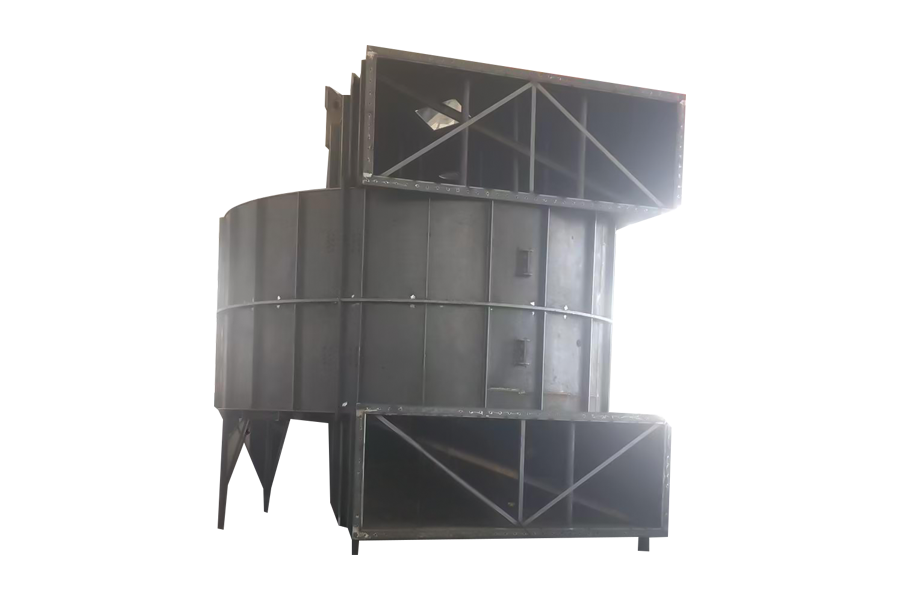 Cement Rotary Kiln Tail High Temperature FanCustom fan for cement kiln tail, moving high-temperature dusty flue gas to stabilize negative pressure, support heat recovery, and protect downstream equipment.View Product →
In an exhaust gas treatment train, the fan's position decides what it must survive. Adsorption and desorption fans move solvent-laden air near ambient temperature. Catalytic combustion fans often sit on the hot side, where gas may reach several hundred degrees. Sealed and purge fans keep the smaller streams balanced.
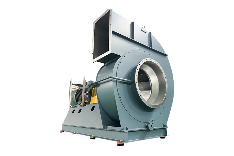 Catalytic Combustion Fan for Exhaust Gas Treatment SystemsCustom fan for VOC exhaust gas treatment, moving gas through catalytic combustion to control flow, reaction temperature, and system linkage with filtration.View Product →
Smelting and roasting furnaces use combustion, cooling, circulation and exhaust fans around the same vessel. Food plants rely on drying, dust removal, powder conveying and tube bundle fans, where cleanability and stable airflow matter more than raw pressure. Grain drying and storage fans run at low pressure but for long seasons, so efficiency and bearing life decide the operating cost.
For the arithmetic behind these duties, see this centrifugal fan selection guide on how capacity, pressure and material choices interact.
Two fans can look identical on a quotation and behave very differently on site. Ask for these explicitly:
The sequence below avoids most surprises. Skipping a step usually means correcting it later with a damper, which wastes energy for the life of the plant.
Where static pressure requirements are high — dense ductwork, long baghouse runs, packed scrubbers — the selection usually lands in the high-pressure range, such as the 809, 912, 919 and 926 series high-pressure centrifugal fans.
Most complaints about centrifugal fans trace back to a few assumptions rather than to manufacturing defects.
A fan quoted for standard air will not deliver the same mass flow in hot gas. At 300 °C the gas is roughly one third as dense as at ambient, so the fan must run faster or be larger to move the same mass. Systems that ignore this arrive at commissioning short of flow.
Oversizing is not insurance. A fan selected well to the right of its duty point follows the curve upward: flow increases, absorbed power increases faster, and the motor may trip on a cold morning when density is highest.
Wear shows up as lost pressure, not as a broken fan. As tip clearance opens and liners thin, the fan drifts off its curve. Comparing current draw and flow against the commissioning record is the cheapest early warning available.
A centrifugal fan is, at heart, a simple machine: a spinning impeller that trades speed for pressure, wrapped in a casing that turns velocity into usable static pressure. The difficulty lies in the operating conditions — temperature, dust, corrosion, sealing and the shape of the system resistance curve. Get those numbers right before the fan is ordered, and the machine will sit quietly in the plant for years.
Your email address will not be published. Required fields are marked*
Main fan Product Name Air volume All-in Medium temperature Conveying medium Main fan 1000-30000...
See Details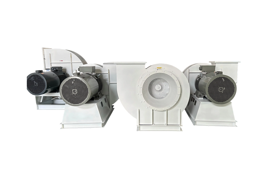
Category: Environmental Protection Industry - Centrifugal Fan for Solid and Liquid Waste Rotary Kiln...
See Details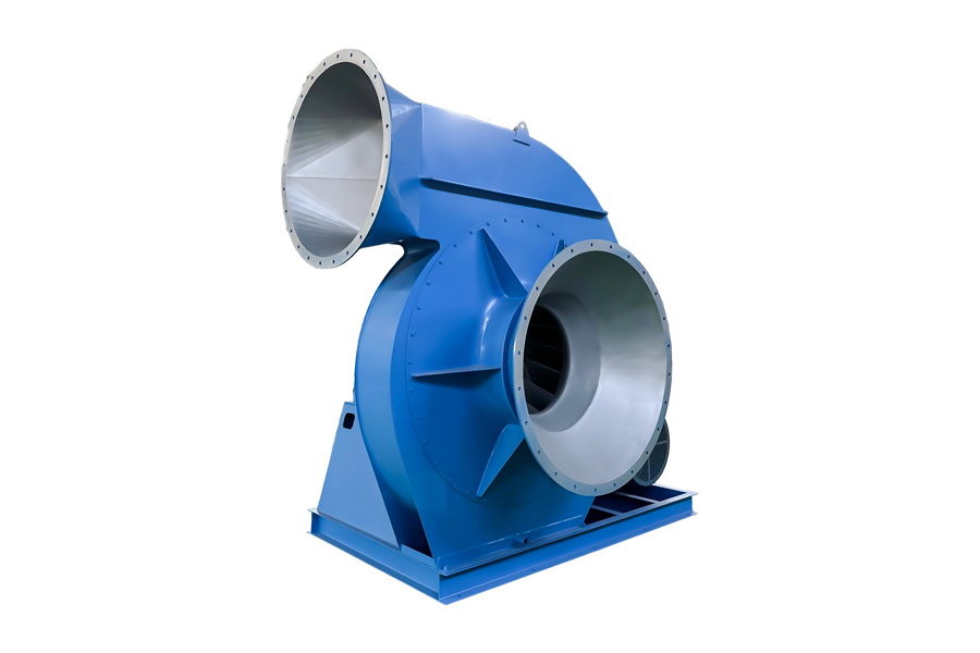
Induced draft fan Product Name Air volume All-in Medium temperature Conveying medium induced dr...
See Details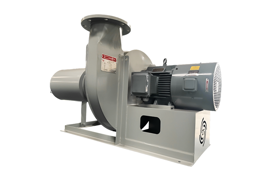
Combustion-supporting fan Product Name Air volume All-in Medium temperature Conveying medium Co...
See Details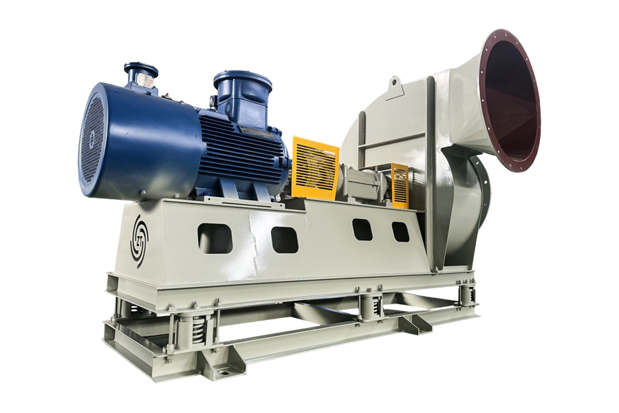
Oxygen supplement fan Product Name Air volume All-in Medium temperature Conveying medium Oxygen...
See Details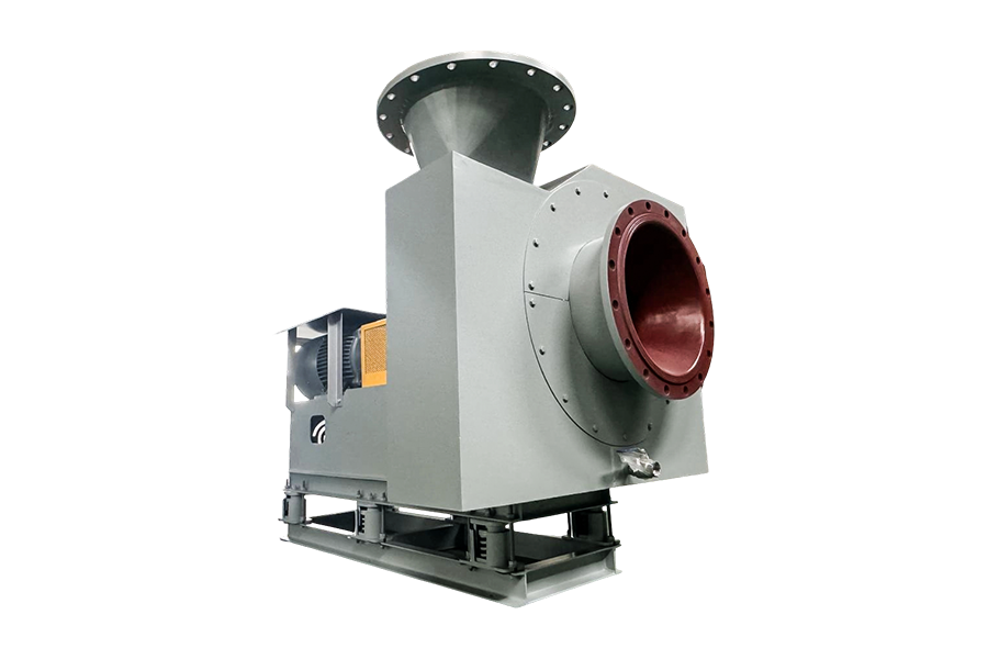
Purge fan Product Name Air volume All-in Medium temperature Conveying medium Purge fan 1000-500...
See DetailsMobile: +86-188 6157 1101
No.58 Wendong Road, Xushe Town Industrial Zone, Yixing City, Jiangsu Province, China

Copyright © JIANGSU ZT FAN CO.,LTD. All Rights Reserved.
Stainless Steel Centrifugal Fan Manufacturers


+86-188 6157 1101
