
 Contact Us
 Language
 English
 русский
 Español
Main fan Product Name Air volume All-in Medium temperature Conveying medium Main fan 1000-30000...
See Details
Content
Suppose you are fitting a centrifugal fan to a dust collection system. The tender specifies 6,000 m³/h of dusty air and a static pressure of 1.5 kPa. The fan arrives, starts, and the motor trips on overload. At the hood, airflow is half of what you expected. This is a common outcome when sizing becomes a lookup exercise on a manufacturer's table.
Centrifugal fan sizing is not a lookup exercise. It is a process of matching the fan's performance curve to the system resistance curve at the actual operating density. Temperature, altitude, dust concentration, duct layout, and the margin policy all matter before you open a catalogue. This guide explains the data collection, operating-condition correction, curve-matching, and motor-power checks that prevent expensive field mistakes.
Start with a clear request sheet. A good sizing request gives the manufacturer enough detail to avoid assumptions. The table below lists the minimum data set for a reliable specification.
| Parameter | Why it matters |
| Volumetric flow (m³/h) | Defines the fan size and impeller width |
| Static or total pressure (Pa) | Defines the pressure rating and speed |
| Gas temperature at inlet (°C) | Changes air density and required power |
| Site elevation and barometric pressure | Corrects the density for altitude |
| Gas composition and dust content | Selects materials and impeller type |
| Noise limit (dBA) | Selects acoustic treatment |
| Mounting and space constraints | Defines orientation and accessibility |
For a more detailed walkthrough of the input parameters, see this centrifugal fan selection guide on capacity, pressure, and materials.
Critical rule: Never size a fan without the actual inlet temperature and site elevation. A fan selected on standard air density (1.2 kg/m³ at 20°C) will be undersized for hot gas or high-altitude installations. The density correction is not optional—it is mandatory.
Most fan performance curves are published at standard air conditions of 20°C, 101.325 kPa, and 50% relative humidity. At 60°C, the density of dry air is roughly 15% lower than at 20°C. If you ignore this, a fan selected at standard density delivers too little mass flow and draws unexpected current for the actual volume.
Use the density correction formula in this simplified form:
Actual density = Standard density × (273 / (273 + T)) × (P_abs / 101325)
Where T is the inlet temperature in °C and P_abs is the absolute pressure at the fan inlet in Pa. The operating point on the fan curve moves with density: the fan produces less static pressure when the gas is hot, and the power draw drops in the same proportion. The system resistance curve also shifts with density.
In practice, add a safety margin of 5% to 10% on the required volume flow and about 10% on the system static pressure. Do not over-margin. A 25% pressure margin can push the operating point into the unstable region of the fan curve, causing surge and noise.
The intersection of the fan performance curve and the system resistance curve is the actual working point. A stable working point should sit on the right side of the peak pressure of the performance curve. If the system resistance estimate is too low, the fan operates at a higher flow and lower pressure; if too high, the flow drops and the motor may overload.
Stability rule: The operating point must be on the right side of the peak pressure point on the fan curve. If it is on the left side, the fan is in an unstable region and will surge, causing vibration, noise, and potential impeller damage.
The affinity laws govern what happens when you change speed:
This means a 20% speed increase raises power by about 73%. If you use a variable frequency drive, check that the motor can provide enough torque at low speeds and that the fan does not cross a critical speed that causes vibration. Always confirm the working point in the chart supplied by the fan manufacturer.
 8-09 Series, 9-12 Series, 9-19 Series, 9-26 Series High-Pressure Centrifugal BlowersAir volume range: 600-5500 m³/h, air pressure: 10,000-20,000 Pa, power: 7.5-75 kW, medium temperature: 20°C, medium density: 1.2 kg/m³.View Product →
Pressure rating is the first differentiator. High-pressure centrifugal fans are used where the system resistance is above about 5 kPa, such as boiler combustion air, pneumatic conveying, or small-diameter duct networks. For those duty points, the 809, 912, 919, and 926 series high-pressure centrifugal fans are built to maintain efficiency and stable operation in the 5–20 kPa range.
Medium-pressure fans suit applications such as kiln exhaust and industrial process air where pressure is between 1 and 5 kPa. Low-pressure fans handle large volume flows with small resistance, such as ventilation and cooling. Check the fan selection chart for each series to identify the right pressure range.
Impeller type also matters. A backward-curved impeller offers high efficiency and lower noise, suitable for clean air. A radial impeller is more tolerant of dust and abrasive particles but has lower efficiency. A forward-curved impeller produces a compact fan with high flow at lower pressure but is not the best choice for demanding continuous work.
Once the working point is fixed, calculate the shaft power:
N = Q × P / (3600 × efficiency)
where N is in W, Q in m³/h, P in Pa, and efficiency is the total efficiency at the operating point. For example, Q = 6,000 m³/h, P = 1,500 Pa, and efficiency = 0.75 gives N = 3,333 W = 3.33 kW. Add a transmission efficiency of 0.98 for direct coupling and a service factor of 1.15, so the recommended motor power is about 3.9 kW.
Motor sizing rule: Size the motor for the worst-case cold start condition (highest density, coldest gas). Size the fan materials for the hot process condition. The motor must have enough starting torque to accelerate the fan from standstill to operating speed.
Remember that the fan curve is normally based on standard air density. If the inlet gas is hot, the actual density is lower, so the pressure generated and the power consumed are lower for the same volume flow. The motor sizing should be based on the worst-case cold start condition, while the fan material must handle the hot process condition. For sustained operation above 200°C, use a fan built with heat-resistant steel, appropriate cooling design, and thermal clearance.
 High temperature centrifugal fanHigh-Temperature Centrifugal FansView Product →
Our custom high-temperature centrifugal fans are designed for furnace exhaust, kiln systems, and similar hot gas streams where standard fans would degrade quickly.
Noise is often an acceptance criterion in industrial plants. A fan running in an unstable part of the curve generates higher noise and vibration. Choose a fan with adequate speed margin and consider acoustic enclosures or silencers when limits are strict. For quiet operation where high efficiency is also required, the ESCF series high-efficiency silent centrifugal fans offer a combination of low noise and low power consumption.
 ESCF series high efficiency silent centrifugal fanAir volume range: 3500-20000 m³/h, air pressure: 550-1600 Pa, power: 1.5-11 kW, medium temperature: 20°C, medium density: 1.2 kg/m³.View Product →
Vibration control starts with the impeller balance grade and the foundation design. A fan that is close to a critical speed can produce resonance. Specify a maximum bearing vibration velocity in the purchase order and request a factory performance test report.
If the gas stream is corrosive or the process demands zero leakage, standard fans are not enough. FRP anticorrosion, stainless steel, Teflon, and zero-leakage custom fans cover these special requirements. Always provide the full gas analysis so the manufacturer can select compatible materials.
Centrifugal fan sizing succeeds when the system and the fan are treated as one integrated unit. Collect the actual operating data, correct for temperature and altitude, match the working point on the curve, and apply a reasonable motor margin. If you are unsure about the system resistance or the fan curve, ask the manufacturer to review the data and supply a curve for your specific condition. With more than three decades of accumulated application experience, our team at Jiangsu ZT Fan Co., Ltd. can help you select the right fan for your process. Browse our general-purpose centrifugal fan catalogue to review standard pressure series, or talk to us for a customised sizing recommendation.
Your email address will not be published. Required fields are marked*
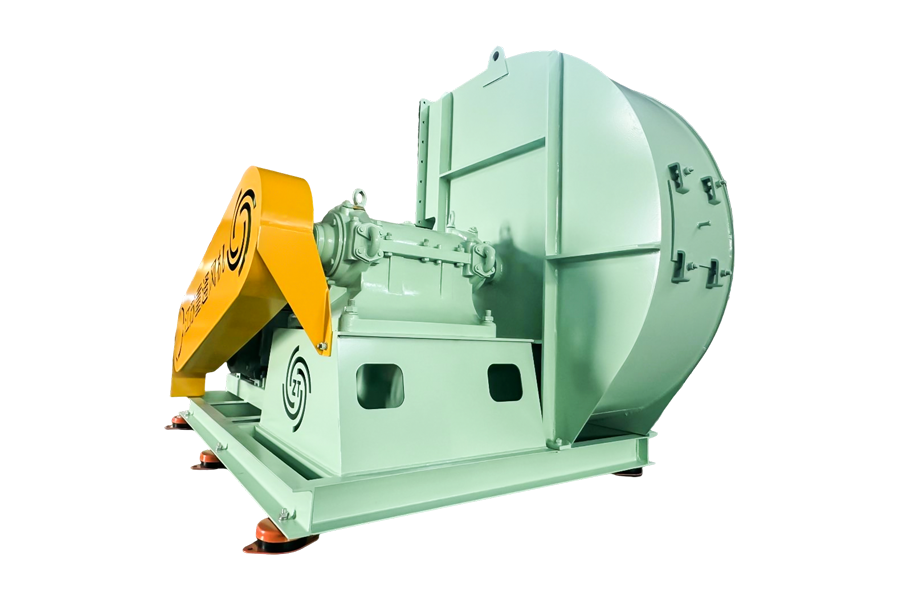
Main fan Product Name Air volume All-in Medium temperature Conveying medium Main fan 1000-30000...
See Details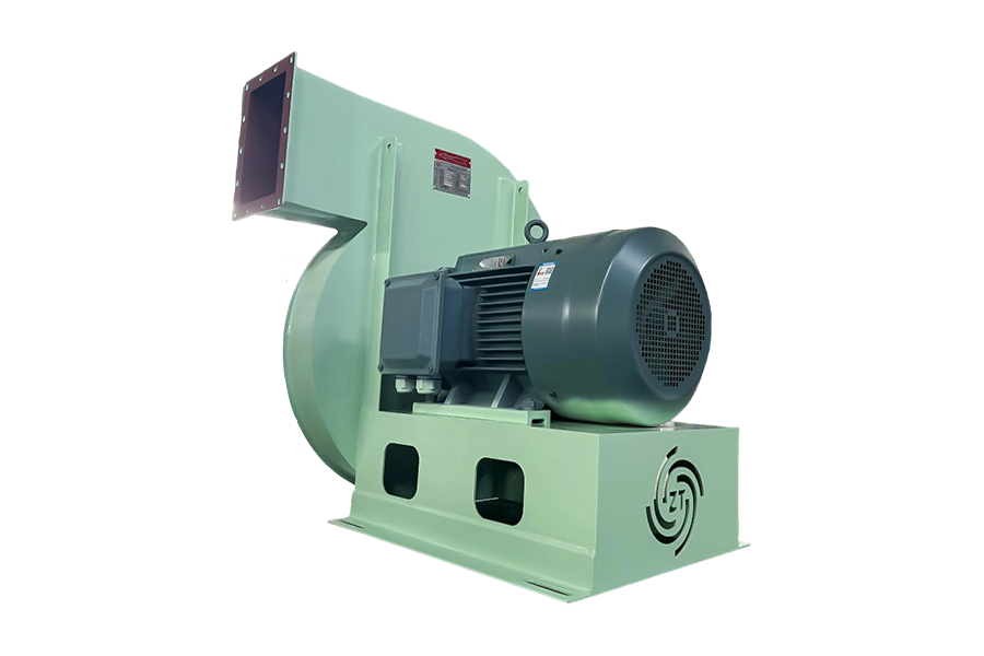
Category: Environmental Protection Industry - Centrifugal Fan for Solid and Liquid Waste Rotary Kiln...
See Details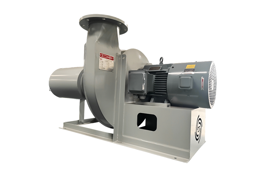
Combustion-supporting fan Product Name Air volume All-in Medium temperature Conveying medium Co...
See Details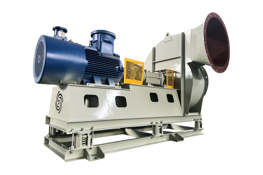
Oxygen supplement fan Product Name Air volume All-in Medium temperature Conveying medium Oxygen...
See Details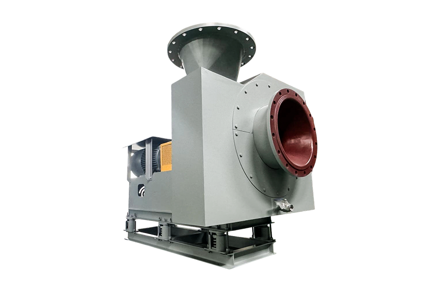
Purge fan Product Name Air volume All-in Medium temperature Conveying medium Purge fan 1000-500...
See Details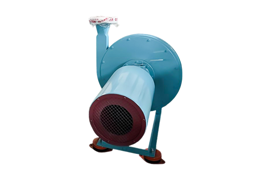
Sealed fan Product Name Air volume All-in Medium temperature Conveying medium Sealed fan 500-10...
See DetailsMobile: +86-188 6157 1101
No.58 Wendong Road, Xushe Town Industrial Zone, Yixing City, Jiangsu Province, China

Copyright © JIANGSU ZT FAN CO.,LTD. All Rights Reserved.
Stainless Steel Centrifugal Fan Manufacturers


+86-188 6157 1101
