
 Contact Us
 Language
 English
 русский
 Español
Category: Boiler System Centrifugal Fan Air blower Product Name Air volume Total pressure ...
See Details
Content
A pneumatic conveying line for cement, flour, or plastic pellets rarely stops at the rotary feeder or the cyclone. In most cases, it stops at the fan. When the actual system resistance exceeds the pressure the fan can develop, air velocity falls below the saltation point, solids settle along horizontal pipe runs, and the line plugs. The difference between a line that runs for months and one that needs weekly cleanout is usually a fan selection decision made before installation. The conclusion you should carry into any pneumatic conveying project is simple: choose the centrifugal fan against the real system resistance curve, not against a nominal pressure table.
A centrifugal fan does not push the product through the pipe directly. It moves air, and the air carries the product. For that to work reliably, the fan must deliver two things at the same operating point: enough volumetric flow to keep the conveying velocity above the settling velocity of the particles, and enough static pressure to overcome every resistance between the material feed point and the final separator. If either value is short at the actual operating point, the system plugs somewhere downstream of the feed point.
Centrifugal fans suit pneumatic conveying because they provide a continuous, steady air stream at a moderate pressure rise. Their performance curves are steeper than those of positive-displacement blowers, which means flow changes noticeably when resistance changes. That is the most common source of confusion: a positive-displacement machine holds flow roughly constant, while a centrifugal fan follows the resistance curve of the installation. The practical effect is that the piping, the filter, and the fan must be developed as one system. If you need a reminder of how industrial centrifugal fans handle airflow and pressure relationships, it is worth reviewing before you fix the specification.
Pneumatic conveying systems are divided into dilute-phase and dense-phase operation, and the fan specification is completely different for each.
In dilute phase, the product is suspended in the air stream at conveying velocities of roughly 15 to 30 m/s. The solids loading ratio is low, and the required fan pressure is typically in the range of 0.02 to 0.15 bar. Dilute phase is simple, flexible, and well suited to long distances. Its downside is wear and particle degradation because the product impacts pipe walls and bends at high speed.
Dense phase moves material along the pipe at low velocity, often 3 to 8 m/s, using a higher pressure at the line inlet. It uses less air and produces less wear and degradation, but the pressure requirement can easily exceed 0.15 bar. Most dense-phase systems rely on positive-displacement blowers or compressors. For short conveying distances and moderate capacities, however, a high-pressure centrifugal fan can still be a workable and lower-cost solution.
| Parameter | Dilute phase | Dense phase |
|---|---|---|
| Conveying velocity | 15 to 30 m/s | 3 to 8 m/s |
| Typical fan pressure | 0.02 to 0.15 bar | 0.15 bar and higher, often above the centrifugal range |
| Solids loading | Low | High |
| Wear risk | Higher at high velocity | Lower |
| Centrifugal fan fit | Good | Limited to short lines and moderate pressures |
The correct method has three steps: calculate the resistance, calculate the airflow, then verify the power and pressure class.
The total pressure loss consists of the inlet hood or filter, straight pipe, bends, vertical lift, the rotary feeder, the cyclone or filter receiver, and the final bag filter. Each of those elements contributes a measurable pressure drop at the design flow. In practice, engineers often underestimate elbows and overestimate straight pipe. A safer approach is to calculate the equivalent length of the line, add everything, and then check with the component suppliers. Add a margin of roughly 10 percent for uncertainty, but avoid excessive oversizing because it moves the operating point to a less efficient area of the fan curve.
Required airflow is the product of the chosen conveying velocity and the pipe cross-sectional area. The velocity must stay above the saltation point for the specific material. Light food powders can convey at around 15 to 18 m/s; cement and sand typically need 20 to 25 m/s; heavier or more adhesive materials need more. If you specify velocity from experience rather than from material data, you are accepting unnecessary plugging or wear risk. A selection guide built around capacity, pressure, and material behaviour is a practical reference at this stage.
Once the required flow and pressure are known, choose a fan whose duty point sits in the stable part of the performance curve. Pneumatic conveying usually moves the specification toward medium-pressure or high-pressure centrifugal fans. The motor power is derived from the volume flow, the pressure, and the fan efficiency, but it must also be corrected for air density. A fan that handles hot process air at 120 °C will draw more power at cold start-up if the motor is sized only for the hot condition. Ask the manufacturer to state the shaft power at both the design condition and the start-up condition.
Material properties affect not only the pipe and the feeder but also the fan construction. Three groups of materials deserve particular attention.
Fly ash, cement raw meal, sand, and recycled aggregates move at high velocity and erode impellers quickly. For these duties, impeller and casing thickness, blade shape, and the availability of wear protection determine service life. A standard low-pressure fan engineered for clean ventilation air will lose performance and balance long before the project reaches its first maintenance interval.
Flour, starch, sugar, grain, and feed pellets create a different set of requirements: smooth surfaces, good sealing, and impeller geometry that prevents product buildup. Food powders also require hygienic design and often a higher level of dust tightness. A food-grade powder conveying fan is built for exactly this kind of duty, with construction details that are difficult to replicate by adapting a generic ventilation fan.
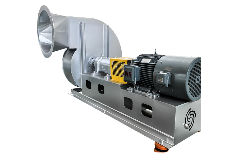 Custom Powder conveying fan for food industry Manufacturers, Factory, CompanyJiangsu ZT Fan Co., Ltd. Is China Custom Powder conveying fan for food industry Manufacturers, Factory, Company, Category: Food Industry ...View Product →
Agricultural conveying lines, which handle grain, seeds, and pelleted feed, usually combine abrasive dust with moisture and combustible material. The agricultural pneumatic conveying fan range addresses these conditions with reinforced housings and sealing that keeps dust away from bearings and external environments.
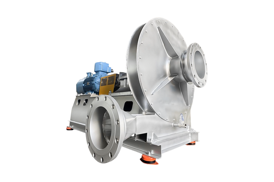 Custom Agricultural pneumatic conveying fans Manufacturers, Factory, CompanyJiangsu ZT Fan Co., Ltd. Is China Custom Agricultural pneumatic conveying fans Manufacturers, Factory, Company,View Product →
Flour, starch, aluminum powder, and many chemical intermediates form explosive dust clouds inside conveying equipment. The fan is not the ignition source in most incidents, but it can be if the impeller contacts the casing or if a bearing overheats. Spark-resistant construction, shaft seals, and proper earthing all reduce the risk. For toxic or very fine powders, a zero-leakage fan configuration is worth discussing early because adding seals later is expensive and often compromises performance.
Before purchase, confirm the following points with the fan manufacturer:
The failures seen on site repeat themselves across plants and industries. The most frequent ones are listed here so they can be caught in the design review:
If you remember only one thing from this article, make it this: build the system resistance curve first, then match the fan curve to it. Do that before discussing impeller material, bearing type, or motor power.
Start with the material, the conveying distance, the routing, and the separating equipment. Convert those into a required flow and pressure. Then choose a centrifugal fan that delivers that duty point with a sensible speed, a stable curve position, and a realistic motor margin. When the project involves difficult materials, high temperatures, or explosive dust, involve the fan manufacturer early. A fan that is selected together with the conveyor layout will run for years; a fan added at the end of the project will keep the maintenance crew busy for all of them.
Your email address will not be published. Required fields are marked*
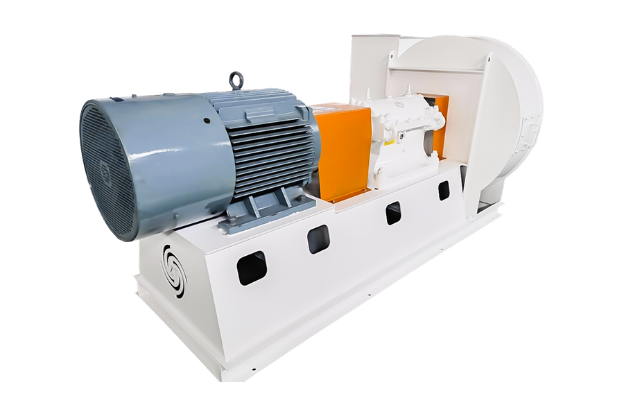
Category: Boiler System Centrifugal Fan Air blower Product Name Air volume Total pressure ...
See Details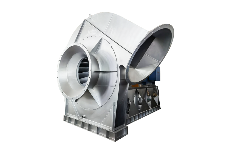
Category: Environmental Protection Industry - Centrifugal Fan for Solid and Liquid Waste Rotary Kiln...
See Details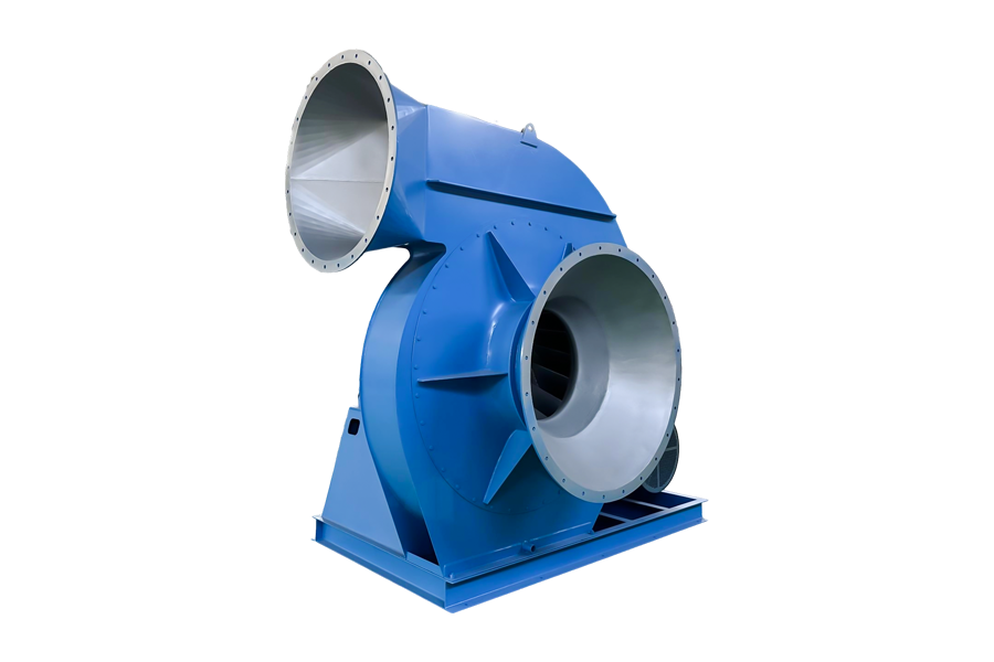
Induced draft fan Product Name Air volume All-in Medium temperature Conveying medium induced dr...
See Details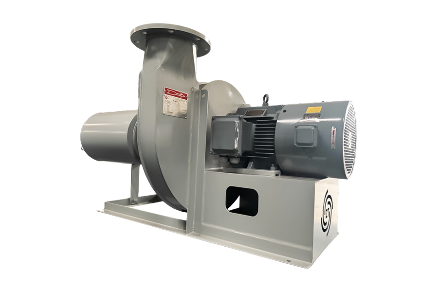
Combustion-supporting fan Product Name Air volume All-in Medium temperature Conveying medium Co...
See Details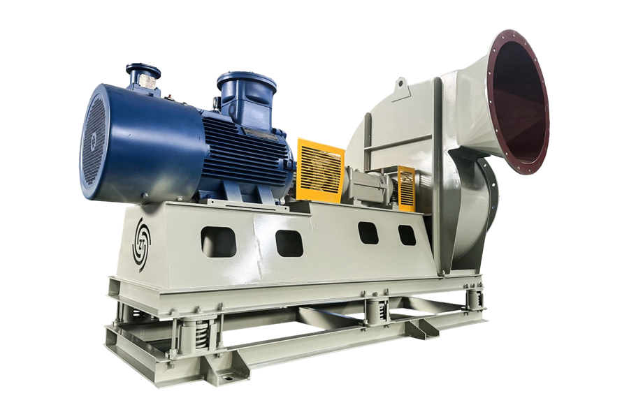
Oxygen supplement fan Product Name Air volume All-in Medium temperature Conveying medium Oxygen...
See Details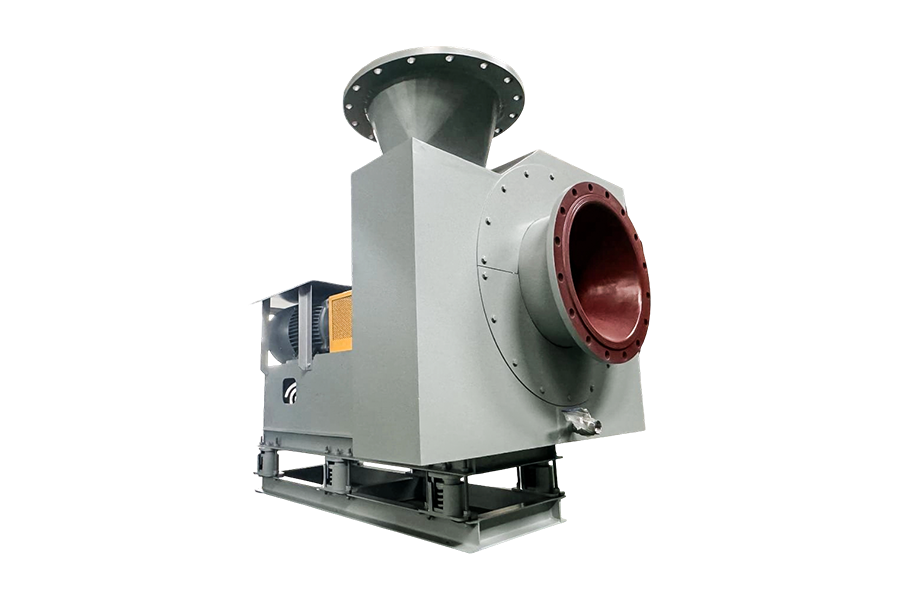
Purge fan Product Name Air volume All-in Medium temperature Conveying medium Purge fan 1000-500...
See DetailsMobile: +86-188 6157 1101
No.58 Wendong Road, Xushe Town Industrial Zone, Yixing City, Jiangsu Province, China

Copyright © JIANGSU ZT FAN CO.,LTD. All Rights Reserved.
Stainless Steel Centrifugal Fan Manufacturers


+86-188 6157 1101
